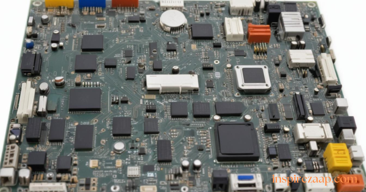
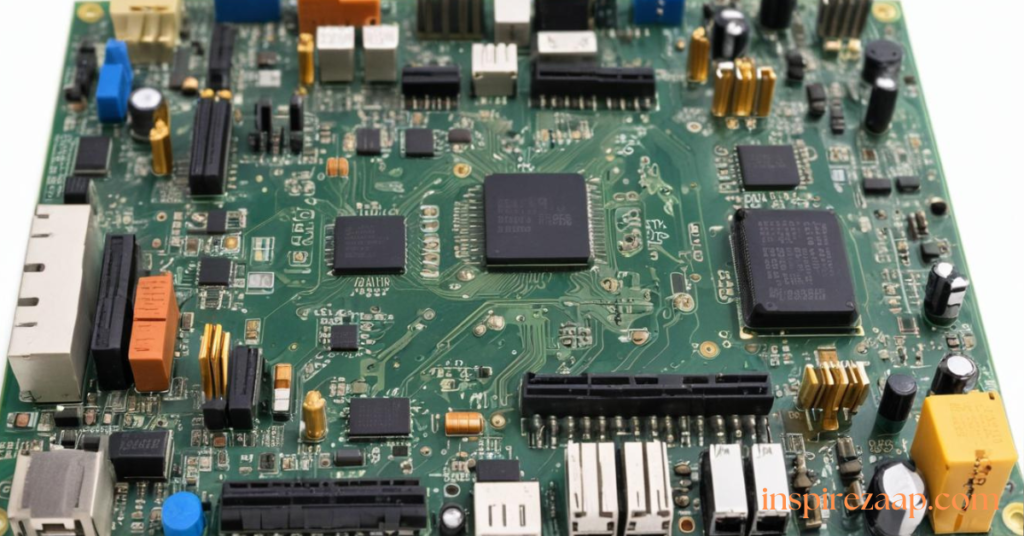
The Flashforge M5 main board is a crucial component of the Flashforge 3D printers, responsible for managing the electrical and communication signals that power various functions of the printer. Understanding the pin outs of this main board is essential for troubleshooting, upgrading, or customizing your printer. In this article, we’ll explain how to identify the pin outs and effectively use them, even if you’re new to 3D printer electronics.
What Are Main Board Pin Outs?
Pin outs are the arrangement of pins on a main board that connect to external components like motors, sensors, and displays. Each pin serves a specific purpose, such as:
- Supplying power.
- Sending or receiving signals.
- Grounding the circuit.
For the Flashforge M5, these pin outs help manage components like stepper motors, endstops, thermistors, and extruders.
Tools You’ll Need
Before identifying or using the pin outs, gather the following tools:
- A multimeter to measure voltage and continuity.
- The Flashforge M5 main board manual or pin out diagram (usually found on Flashforge’s official website or user forums).
- A screwdriver set to open the printer’s casing.
- Safety equipment, such as an anti-static wrist strap, to protect the board.
Identifying Flashforge M5 Main Board Pin Outs
1. Locate the Main Board
- Turn off the printer and disconnect it from power.
- Open the printer’s casing to access the main board.
- Identify the main board by its label, usually printed with “M5.”
2. Refer to the Diagram
A pin out diagram is essential for understanding the board’s layout. If you don’t have one, check the official Flashforge documentation or online resources such as community forums.
3. Examine Pin Labels
- Many main boards have pins labeled directly on the PCB (Printed Circuit Board). Look for terms like “X-Motor,” “Y-Motor,” “E-Stop,” or “Thermistor” next to the pins.
- Use the pin labels to match them with their respective components.
4. Test with a Multimeter
If labels are unclear or missing:
- Set the multimeter to measure voltage or continuity.
- Check the power pins for consistent voltage output (typically 12V or 24V).
- Use continuity mode to trace connections and confirm their function.
Using Flashforge M5 Main Board Pin Outs
1. Connecting Stepper Motors
- Identify the motor control pins (e.g., X, Y, Z, E for extruder).
- Plug the motor cables into their respective ports. Ensure the wires are aligned correctly to avoid incorrect operation.
2. Wiring Endstops
Endstops signal the printer when an axis reaches its limit.

- Locate the endstop pins (labeled as X-STOP, Y-STOP, etc.).
- Connect the endstop switches, ensuring the wiring matches the diagram.
3. Thermistors and Heating Elements
Thermistors monitor temperature, while heating elements control the printer’s bed and extruder.
- Plug the thermistor wires into the appropriate pins (usually marked as TH1 or TH2).
- Connect heating elements to their designated ports, ensuring secure connections to avoid faults.
4. Adding or Replacing Fans
Fans are essential for cooling. Use the labeled fan pins (e.g., FAN1, FAN2) to connect the wires. Verify the voltage matches your fan’s specifications.
Troubleshooting Common Issues
-
Unresponsive Components
- Check if the pins are securely connected.
- Use a multimeter to test for power or signal transmission.
-
Incorrect Wiring
- Double-check the diagram to ensure each wire is in the correct pin.
- Swap polarity if motors or fans run in reverse.
-
Overheating
- Inspect the connections to the heating element and thermistors.
- Replace damaged wires to prevent short circuits.
Tips for Safe Handling
- Always power off the printer before touching the main board.
- Use insulated tools to prevent accidental shorts.
- Document your connections to avoid confusion during reassembly.
Conclusion
Understanding and using the pin outs on the Flashforge M5 main board can significantly enhance your ability to maintain and customize your 3D printer. By identifying the pins with the help of diagrams and testing them with tools like a multimeter, you can ensure proper connections for motors, sensors, and other components.
Whether you’re troubleshooting or upgrading, following these steps will help you work confidently with your Flashforge M5. Stay safe, refer to official resources, and enjoy the improved performance of your printer!


